

Understanding Golf Shaft Stiffness
By Russ Ryden, Fit2Score, A Dallas Fort Worth Club Fitter & Club Maker
The Golf Center at the Highlands, Carrollton Texas
How stiff is this golf shaft? That question is on the mind of anyone who has ever been curious about their golf clubs. Club makers have been trying to answer that question for a long as I can remember.
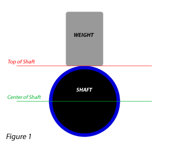
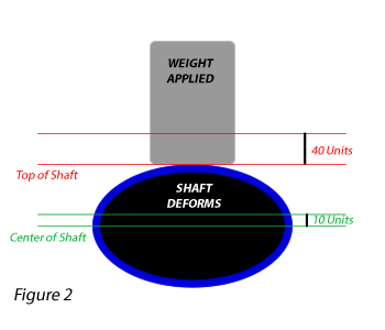
 I am told the first tool commonly used was a deflection board. The butt of the shaft is clamped, a weight is hung on the tip and the amount the shaft bent was used to rate the shafts stiffness. This was and still is, an excellent way to rate shafts. The problem was that none of the shaft companies used the same board. Shaft sales and marketing created a letter system, LARSX, Ladies, Amateur, Regular, Stiff, X-Stiff. Brunswick shaft company patented a numbering system 4.0, 4.5, 5.0, 5.5, etc. The golfer was and still is confused about these numbers. The club making community made their own attempt at creating a standard. To date, the only standard is confusion.
I began my journey to understand the golf shaft about 15 years ago. I now have a database containing measurements of about 3000 different shafts. For those that are looking for a simple basis for comparing shafts I have adapted a method recommended to me by Jeff Meyer, Area Under the EI curve. Jeff has spent most of his life in the golf shaft business. The idea came to him when he was the shaft guru at Acushnet Golf.
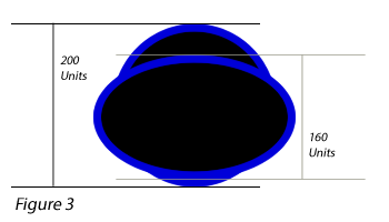
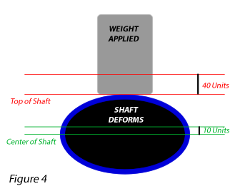
As you watch this animation, you will understand the concept.
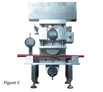
The best ideas are often the simplest. Area under the EI curve is easy to compute once you have the inch by inch measurement. You add them up. To compensate for shafts of different lengths you divide the sum by the length of the shaft measured. To create a simple index, I divided that number by a common factor to create an easy to compare 2 digit stiffness index.
The recent reviews presented here at Golf Shaft Reviews, give a stiffness index for each shaft measured.
One of my friends, a fellow fitter who has been working with EI graphs since the very first day I began measuring them asked why I would reduce the elegance of the EI profiles to a single number. My answer, if you are going to use a number to try to understand shaft stiffness, be it LARSX or 4.0, 5.0, 6.0 7.0. area under the EI curve is a better number. It indicates all of the shaft, not just a single point. Is it the best way we now have available? No. Knowing the shape of the EI curve and its relationship to other shafts is the best way we now have available. But without knowing and studying the EI profiles of the 3000 shafts I have already measured, it is better than the alternatives. And given that the measurements were all taken the same way with the same instrument, it transcends manufactures, models and weights.
Lets lets look at some of the other ways shaft stiffness is presented and marketed.
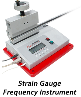
Shaft Frequency
The concept of using shaft oscillation frequency was discussed in the 1968 book, “Search for the Perfect Swing” by Alastair Cochran and John Stobbs. “Search for the Perfect Swing” is one of the first explorations of golf technology. In Appendix I a formula for frequency is shown as a function that included “E=an elastic property of the material of the shaft” and “I=a quantity which depends on the precise cross-section of the shaft and which represents its ability to resist bending”. As you read this article you will realize the authors were saying frequency might be useful, but the complexity of the calculation was not likely to make frequency an easy way to define golf shaft stiffness.
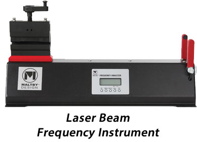 Dr. Joe Braly introduced club makers to using the rate of oscillation of a shaft (frequency) to understand its stiffness. In the 80’s he did research on the PGA tour. He used a frequency instrument to measure the shafts used by the tour players. From this research, he developed a formula for the stiffness of ratio of the different irons in the set. The ratio he found was 4.3 CPM (cycles per minute) per one half inch of length of club.
 Inspired by the research done by the Braly’s, a club makers organization, the PCS, endorsed and taught frequency based club making to its many, many members. it was a time when shaft design was not as complex as it currently is and when frequency instruments were one of the few tools available to club makers for measuring shaft stiffness.
The PCS recognized that frequency measurements were affected by clamp pressure, clamp length, weight and the actual instrument being used. They established a standard primarily focused on one of the instruments. Software knows as “The Equalizer” was sold to PCS members. It came with a calibration stick that was used to standardize the readings to a common denominator across instruments. During its dominance as a club makers organization the PCS did not promote discussion of alternative shaft stiffness systems. Nor did it inform its membership that the shaft designers and manufacturers primarily used EI for understanding shaft stiffness.
Let’s take a look at an EI chart of three shafts with the same frequency.Each of these shafts has a frequency of 354 on my instrument. I use a pneumatic clamp, clamped 7″ from the butt of the shafts. These are 6 iron shafts and were measured with a 261 gram 6 iron head. Seven inches, the Fujikura standard, is still used by some club manufacturers and shaft companies.
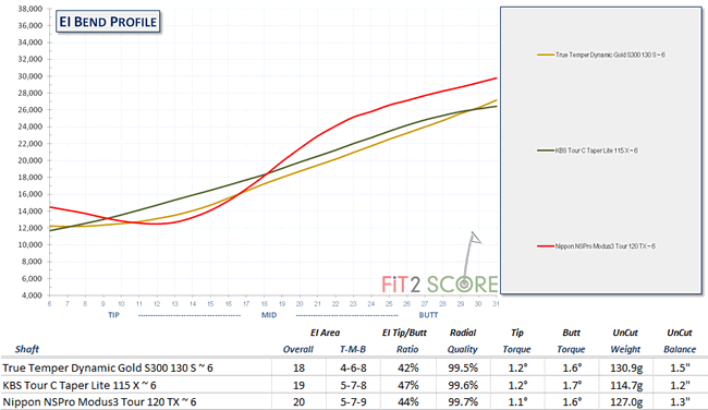 As you can plainly see, these three shafts which have exactly the same frequency are quite different when viewed with EI analysis. Tom Wishon, then at GolfSmith, recognized that butt frequency alone did not work. He measured frequency at several points down the shaft while sorting a box of iron shafts for a set he was building for a PGA tour pro. That evolved into a system of measuring the shaft with a frequency instrument at different point down the shaft. With that, the term ‘shaft profiling’ was born. That system was flawed in more ways than I want to discuss here. It gave very crude charts of stiffness down the shaft when compared to EI charts. If you want to understand the relationship and the difficulty of using frequency to estimate EI read page 205 of Cochran & Stobb that I referred to at the beginning of this section.
Shaft frequency is not of much use in evaluating shaft stiffness. The problem for club makers and fitters who recognized the importance of shaft profiling was that there was not an affordable EI instrument until I designed and manufactured one. They used the frequency instruments they had. As with all technologies, instruments and expertise evolves. Frequency profiling and frequency rating of shaft stiffness were an attempt by club builders to reverse engineer shaft knowledge not shared by the shaft companies. Affordable EI instruments have closed the knowledge gap between the shaft engineer and the club fitter.
Shaft Stiffness Labels – LARSX
Most shafts have a stiffness label. These labels are referred to as LARSX by club makers, Ladies, Amateur, Regular, Stiff, X-Stiff. As we all know, there is no standard for assigning stiffness between manufacturers. But what you may not realize is that there is no standard for assigning these labels to different products made by the same manufacturer. Let’s look at three different KBS shafts all labeled S flex.
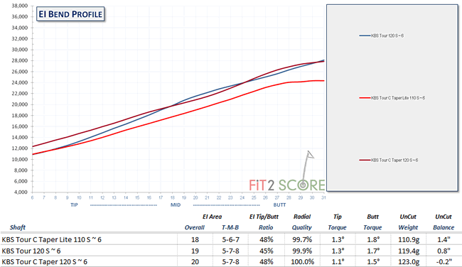 As you can see, the KBS 120 gram Tour and C-Taper have very similar stiffness at the butt. The 110 gram C-Taper Lite also labeled S flex is much softer throughout the shaft. This is quite common. KBS shafts were at hand when I was measuring and creating charts for this article, they are not unique in this practice, all shaft companies do this. To make any sense out of shaft company labels you must recognize that LARSX refers to shaft stiffness of that particular model and weight, It does not apply to shafts of different models or weights.
What you might have started to notice here is that Jeff Meyer’s system, area under the EI curve, as a single metric rating system, actually makes some sense.
Shaft Stiffness Labels – 4.0 ~ 4.5 ~ 5.0 ~ 5.5 ~ 6.0 ~ 6.5 ~ 7.0
The Rifle shaft produced by FM precision/Brunswick/Royal Precision (different names, same company) introduced and patented a numeric stiffness rating system. It was a detailed system for relating swing speed to shaft stiffness. Using shafts that were both weight and frequency sorted in the factory, the club maker made iron shaft sets by matching swing speed to shaft stiffness. It was revolutionary in its day. The first systematic attempt at shaft fitting. There are many club makers that still use the Rifle system or variations of it.
The Royal Precision shaft company was purchased by True Temper and with that purchase was the numeric stiffness rating patent. Here is a look at how that system is currently applied.
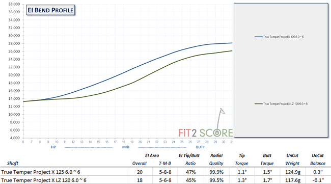
Two shafts, the Project X and the Project X LZ are both labeled 6.0. The EI measurement clearly shows these shafts have different stiffness. Once again, we see that stiffness labels on shafts show the difference in shaft stiffness within models not between models.
Now, let’s loop back to butt frequency and add another shaft to this chart.
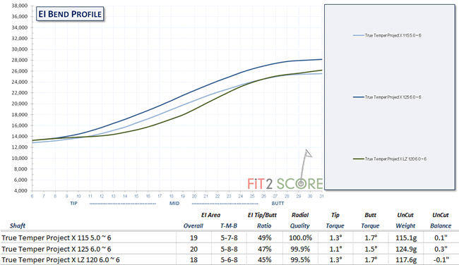
The frequency of these three shafts is Project X 5.0 = 350, Project X 6.0 = 363 and Project X LZ 6.0 = 349. Notice how the Project X 5.0 and the Project X LZ 6.0 are similar in the butt area, having the same butt frequency. They are quite different in the mid zone. And once again, take note of the EI area rating of these two shafts.
Conclusion
Back to the question posed in the opening sentence of this article, How stiff is this golf shaft? The systems we have to rate golf shaft stiffness do not work across brands or even across models within brands. Most experienced club fitters use their experience to understand golf shaft stiffness. Many use some systematic method, most often frequency, to rate the shafts they work with. Then with that rating in mind, they test golfers performance and reaction to various shafts. A sense of what works and does not work develops through experience and is indexed by the shaft labels or their shaft stiffness rating method. The current key to understanding shaft fitting is experience. Years of experience. Because there was no current system that accurately indexes the stiffness of the golf shaft.
Now, thanks to Jeff Meyer, there is.